Abstract
This paper presents an application case of Image-Based-Modeling to create a 3D virtual model of an existing physical building model. The reverse engineering process involves measuring an architectural physical model and then reconstructing it as a 3D model by means of several photographs taken around the existing object. Then, the 3D model has been imported in a CAD software in order to do technical drawings
Introduction
Computer-Aided Design(a) has evolved a lot since its origins in the Seventies [1]: its interaction with powerful computers allows the management of huge functions having heavy numerical calculations. As a consequence, the building design process is undergoing deep modifications because of the use of increasingly powerful computer tools.
Nowadays contemporary architects tackle new modeling methods modifying definitively the knowledge of architectural shapes and the act of planning. That does not mean that traditional drawing techniques are definitively abandoned. However, if on one side drafts continue belonging to the building design process, on the other side vectorial drawings and digital renders take the place of handmade sections, plans and perspective views [2].
Current technologies
Several methods have been developed in the wide panorama of 3D modeling: triangulated surfaces, parametric curves, bicubics, Coons patches, Bézier curves and patches, B-splines and NURBS. Finally, all these kinds of curves and surfaces can be realized more quickly by means of digital methods rather than analogical ones. Moreover, CAD software based on surface approaches becomes the essential design tool in the fields of automobile, aeronautics and nautical [3].
Digital era and computer graphics influence also the field of architecture: the contemporary architect starts leading the shape beyond simple and standard geometries [5]. The impossible calculations of the Eighties become finally conceivable. Curved shapes become striking. New architectures challenge gravitational force and new materials resistance.
The role of the scale model
Architects cannot limit themselves to analyzing a formal architecture represented in a digital space. They need to understand, to evaluate and to verify shapes and proportions. The 3D model proves unsatisfactory. On the other hand, the scale model assumes the checking role of the formal choices previously defined on plans or established by 3D model deformations. This is the case of the buildings such as the ones of John Utzon, Rem Koolhas or F.O. Gehry.
For example, F.O. Gehry uses a hybrid process which is based on a precise three-dimensional feeler that surveys scale model points, sides and surfaces. Once coordinates (points cloud) have been imported in Catia(b), mathematical curves are drawn as near as possible to the coordinates detected on the scale model. Then, various rapid-prototyping techniques can be used to create new scale models that will be finally compared to the original ones. This process is repeated several times until the desired shapes are obtained [4].
In the beginning, the reverse engineering methods adopted to shift from the scale to the digital model were currently used in various fields of industry: the aim was to carry out shape and materials resistance verifications. For a few years, the architecture field has exploited these techniques. However, costs of reverse engineering machines are still too high(c).
The approach
Today new hybrid and cheaper methods can be used: they can be considered as simplified shape surveys having a fulfilling precision level. By means of simple photographs, photomodeling allows measurements to be caught and objects to be modeled by means of geometrical calculation algorithms and image processing.
This method proposes photomodeling as a reverse engineering solution: starting from multiple snapshots around the scale model, the user can register a set of coordinates located on the object surfaces, creating a sort of point cloud. In this way, it is possible to take measures, to rebuild the 3D model and finally to add technical details on it. In the following paragraphs this method will be detailed on a concrete example: a scale model produced for an architectural study. The goal of this work is to recover the spatial coordinates and later to model surfaces and details, by keeping the same proportions of the scale model. The method is defined by the following steps.
-
•Snapshots around the scale model. The first step consists in taking pictures around the scale model: the only constraint is that the object should be completely visible in each photo. For a good acquisition of spatial coordinates, the minimal number of photos is 8: 4 snapshots are taken according to principal axes and 4 ones according to diagonals. Other snapshots can be added if the physical model is rather complex, or in case interior walls and grounds should be surveyed. In this example, the scale model has been created in order to show the internal spatial distribution so its various floors can be removed to show the interiors for each level: -1,0 and 1. The overall photos are 8 for each floor, so they are 24 in total.
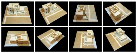
Figure 1. Snapshots around the scale model of an architecture case study.
-
•Photo calibration and orientation. In this phase, photos have been calibrated two by two. In order to do this, 8 check-points have been placed between the first two photos and cameras have been automatically calibrated. That means that camera positions have been found in the 3D space. Once the first two photos have been calibrated, all the other ones will be calibrated by adding 4 points on each couple of photos. Between the first and the last snapshot, four final points should be added in order to reduce the error due to the manual positioning of points. As a result of the calibration, spatial coordinates describe the architectural object. At this stage, if the scale model is based on simple geometrical shapes, coordinates can be exported for modeling software in order to design the virtual model. On the contrary, if the model is based on curved shapes, the collect of points should be thickened in order to export a more important point number. In this case study we chose to continue modeling in the photo modeling software.
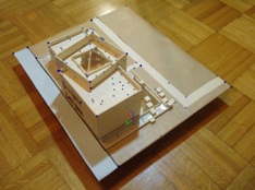
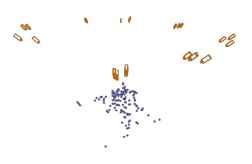
Figure 2. a) Check-points detected on each snapshot permit to define spatial coordinates on the scale model. b) Calibration allows cameras to be positioned in space.
-
•Surfaces modeling and export in dwg format. After the snapshots calibration, a Cartesian system can be defined and the measuring unit can be affected to the scale model. The object can now be modeled by means of the polygon creation tools and the cutting tools such as split face, extrude face, create face or add primitives. The architectural shapes are conceived according to their function: that means that step stairs, exterior and interior walls, pillars, roofs and floors are conceived as separated elements. However, the model is constructed using thin pieces of wood, cardboard, paper and glue. As a consequence, the reconstruction of the geometrical model starting from a physical model prevents the virtual model from being really precise. At last, the 3D model has been exported in dwg format in order to add details in Autocad.
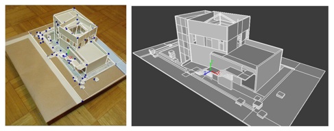
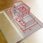
Figure 3. 3D model created in the photo modeling software leaning on 3D coordinates and geometrical shapes.
-
•Details creation. At this stage, the 3D model can be opened in various modeling software in order to add technical details. As shown in figure 4, some detail elements concerning casings and windows have been added to the original 3D model. However, according to the modeling software used, the imported geometrical shapes are not always well-adapted to undergo modifications: actually some software supports a boundary representation(d), some other one the Constructive Solid Geometry method(e) and at last other software supports both methods. That means that if there is any method incompatibility between the photo modeling and the modeling software, architectural elements should be drawn again instead of being modified.
Figure 4. 3D model imported from the photo modeling software into modeling software: details have been added in the last application.
Conclusion
The adopted method underlines two fundamental aspects.
Firstly, this example confirms that simple snapshots can be an efficient way to extract relevant information about geometrical shapes: in particular, extracted data is represented by spatial coordinates. All these 3D coordinates correspond to a point cloud that can be more or less rich according to the geometrical complexity of the model. With this meaning, the photo modeling process gains the role of reverse engineering tool.
Secondly, today it is necessary to think about modeling as a hybrid spot. In other words, according to the goal of the project (two-dimensional plans or three-dimensional restitutions), it becomes increasingly necessary to pass by several techniques (analogical and digital) and by several software (calibration, 3D modeling, render software, etc).
On the other side, this method underlines a weakness in the approach.
If the computer programs adopted in this hybrid approach use incompatible modeling methods, the 3D model exploitation becomes really binding. Two solutions are possible. On one hand, the 3D model should be exported in compatible software, in order to add details and modify the geometry, but often compatible software are not adapted to enrich the model with technical details. On the other hand, just spatial coordinates should be exported from the photo modeling software in order to reconstruct surfaces with higher performance modeling software.
Therefore, there is a definite need for integrating these utilities in a single application taking into account all these features.
(a) CAD involves software and geometric modeling techniques permitting to conceive, test virtually and produce manufactures and tools.
(b) Catia (Computer Aided Tridimensional Interactive Application): is a multi-platform CAD/CAM/CAE commercial software suite developed by the French company Dassault Systemes. CATIA uses a non-manifold solid engine. It use piecewise polynomial surfaces but later versions implemented NURBS.
(c) Reverse engineering costs vary according to the manufacture technique and the adopted material: 3D printing, wax injection and Fused Deposition Modeling belong to the cheapest techniques; the subtractive and some of the addictive techniques such as Selective Laser Sintering, Stereolithography and Laminated Object Manufacturing are the most expensive.
(d) The object is represented by a complicated data structure giving information about each of the object's faces, edges and vertices and how they are joined together.
(e) CSG method is a modeling technique which volumes are created in by the application of Boolean operations (union, intersection and difference)
[1] Mitchell, W.J. Computer aided architectural design, Petrocelli Charter, 1977.
[2] Quintrand P. et al., La conception assistée par ordinateur en architecture, Traité des Nouvelles Technologies, Hermes, 1985.
[3] http://www.cadazz.com/cad-software-history.htm
[4] Mitchell W. J., Roll Over Euclid: how Frank Gehry Designs and builds, In Frank Gehry, Architect, ed. J.Fiona Ragheb, 352-363. New York: Guggenheim Museum Publications, 2001.
[5] Farin, G., A History of Curves and Surfaces in CAGD, Handbook of Computer Aided Geometric Design.
[6] Górska R. A., Computer aided modelling to solve certain design problems, Biuletyn Polskiego Towarzystwa Geometrii I Grafiki Inźynierskiej, Zeszyt 12, 2001, pp. 18-21.
[7] Bellu S., 500 voitures extraordinaires; l'aventure du concept car, Édition Solar, 2002.
Chiara Stefani- June 2009 - Portal of Architectural Image-Based Modeling
Between the scale model and the digital model
An hybrid approach for architectural design
Chiara Stefani, UMR CNRS/MCC 694 MAP-Gamsau
chiara.stefani@gamsau.archi.fr